
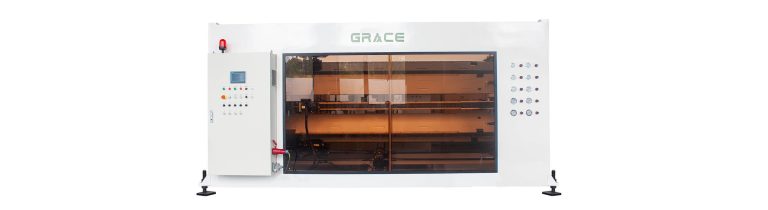
PRODUCT OVERVIEW
Designed around the production task.
Stable pipe traction with controlled grip and synchronized drive, designed to protect pipe quality through production.
EQUIPMENT REFERENCE
Confirmed equipment, followed by the process context.
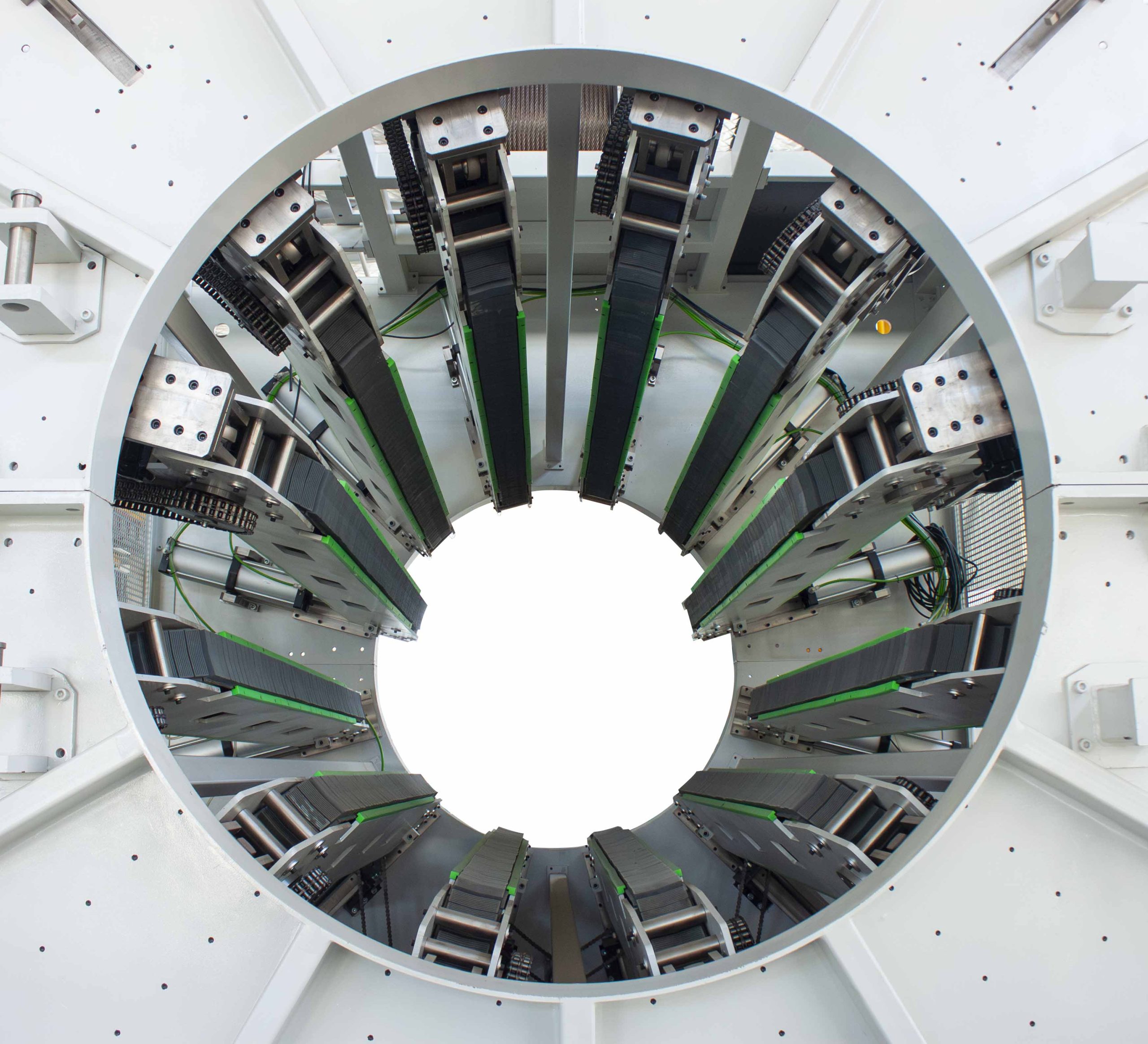
Stable pipe traction
The haul-off unit provides controlled traction through the downstream line. Its configuration is reviewed against pipe diameter, wall thickness, line speed and the required surface protection.
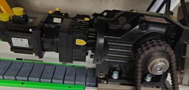
Independent servo-driven tracks
Independently driven tracks can be configured for synchronized pipe handling. Drive arrangement and control logic are selected for the applicable line and pipe specification.
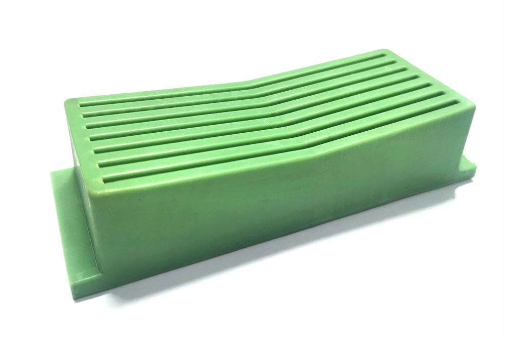
Anti-sag rubber blocks
Anti-sag rubber blocks provide controlled contact with the pipe, helping protect the surface while maintaining stable traction through the production process.
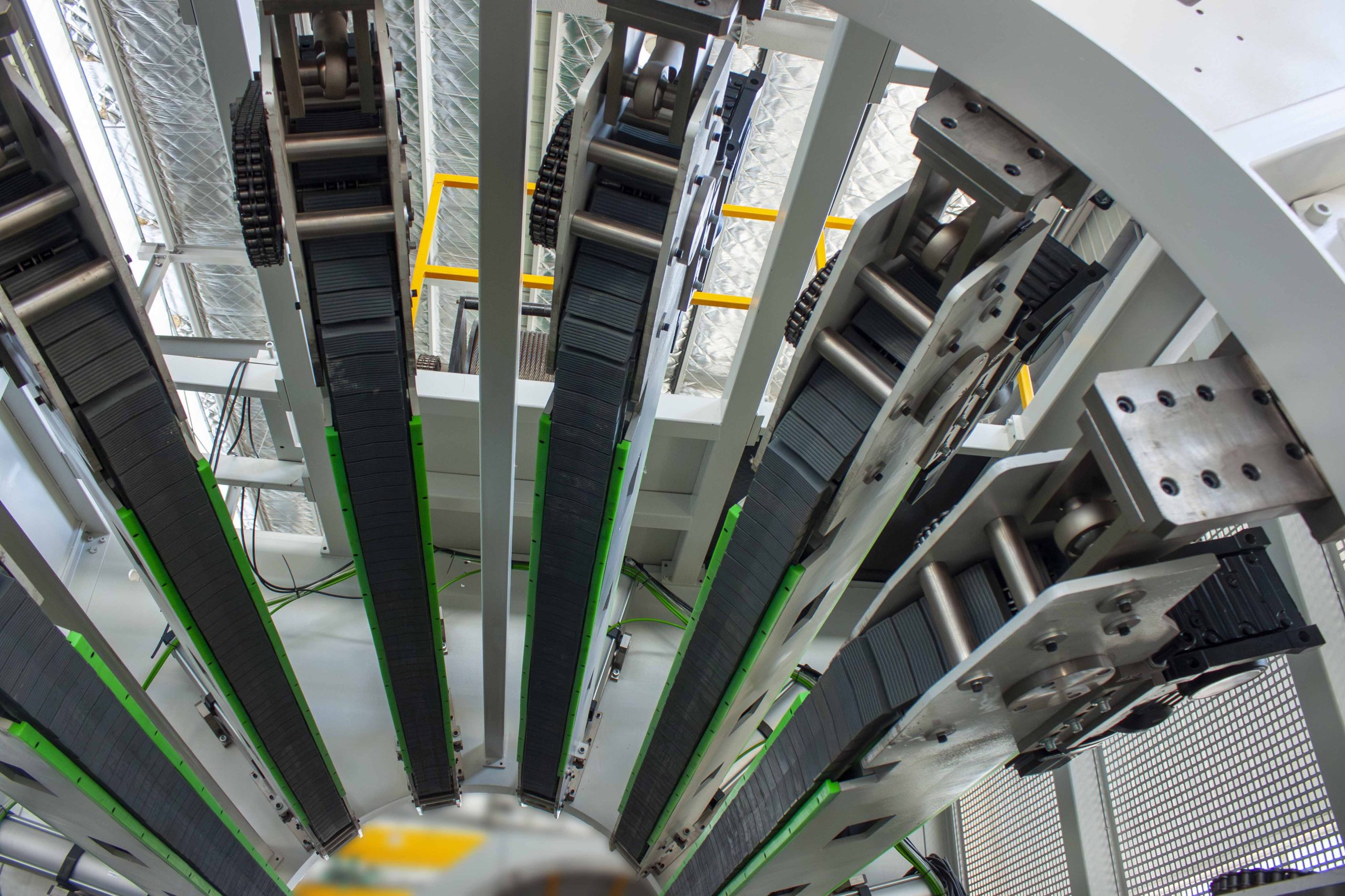
Anti-sag chain arrangement
The chain and guide arrangement is designed to support controlled track movement and practical maintenance. Final configuration is matched to the haul-off size and operating conditions.
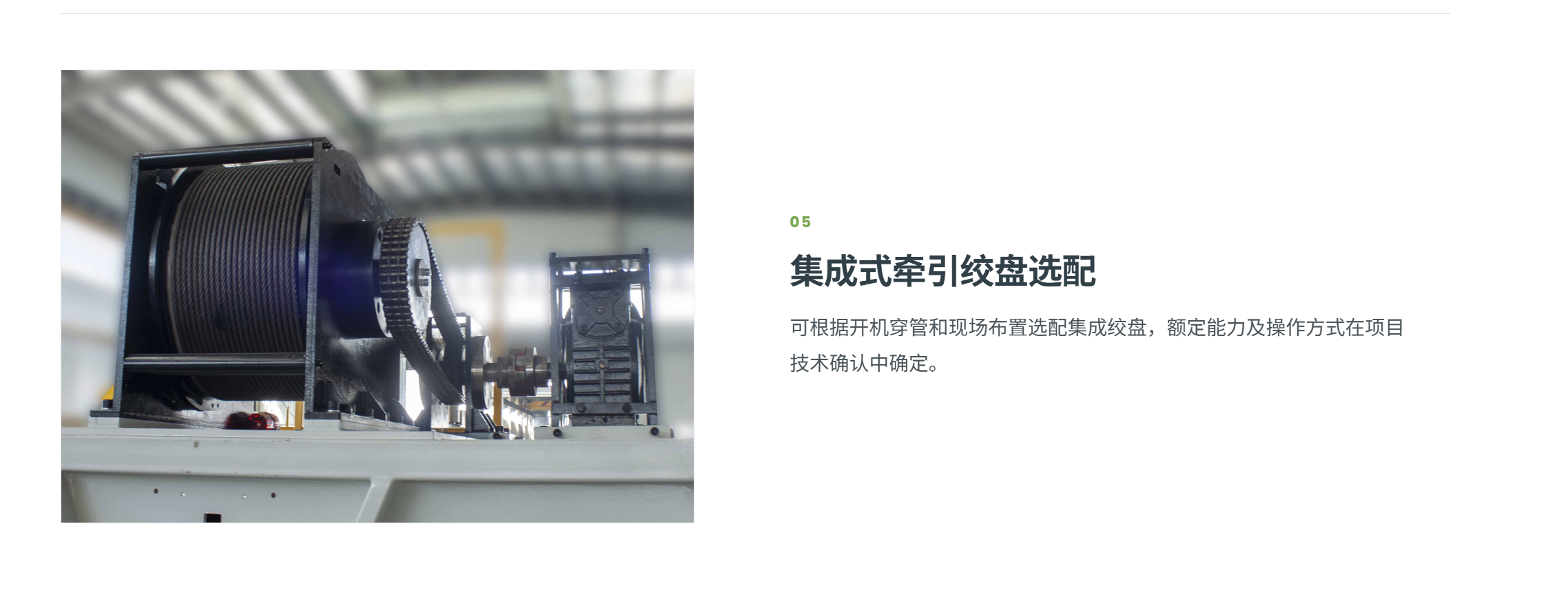
Winch
A winch can be specified where it supports pipe guiding and start-up handling. The option is confirmed against the project layout and operating procedure.
CONFIGURATION ENGINEERING
Selecting pipe traction from weight, surface protection and line conditions
The haul-off is selected to keep the pipe moving in step with extrusion, cooling and cutting while protecting the finished surface. Track arrangement, contact length, pulling duty and control interface are reviewed against the actual pipe and line conditions.
Pipe weight & traction duty
Material, outside diameter, wall thickness, line speed and the required surface protection establish the traction task. The final haul-off is selected from the complete pipe schedule rather than maximum diameter alone.
Track arrangement & contact
Track number, contact length, contact material and support arrangement are reviewed to provide controlled grip while protecting the pipe surface. The configuration follows the applicable pipe range and downstream duty.
Line synchronisation
The haul-off is integrated with extrusion, cooling and cutting controls so the complete line operates from one coordinated production condition. The required interface is defined for the selected line configuration.
Start-up & handling options
Pipe support, guide and start-up arrangements can be configured where the project layout or pipe handling procedure requires them. Their scope is confirmed with the factory layout and operating process.
FOR A TECHNICAL PROPOSAL
Information that lets us define the right line.
- Pipe material, complete size / wall schedule and finished surface requirement
- Target line speed and product handling method
- Required pulling duty and available equipment layout
- Cutting, marking, packing and downstream interface
- Control architecture and required automation
- Factory operating and maintenance conditions
Model data is a preliminary selection guide. Pulling duty, surface marking, speed range and final track configuration are verified against the actual pipe, complete line and agreed project conditions.
TECHNICAL DATA
Representative pipe haul-off model range
| Model | Pipe range | Tracks | Speed range | Contact length | Max. pulling force |
|---|---|---|---|---|---|
| GMHO63B-S1.5/2 | φ16–63 mm | 2 | 0.1–34 m/min | 1,000 mm | 6,000 N |
| GMHO160B-S1.5/2 | φ20–160 mm | 2 | 0.1–31.4 m/min | 1,500 mm | 10,000 N |
| GMHO250B-S1.5/3 | φ50–250 mm | 3 | 0.1–12.25 m/min | 1,700 mm | 12,000 N |
| GMHO315B-S1.5/4 | φ75–315 mm | 4 | 0.1–12.25 m/min | 1,700 mm | 15,000 N |
| GMHO400B-S1.5/4 | φ90–400 mm | 4 | 0.1–8.62 m/min | 2,300 mm | 22,000 N |
| GMHO450B-S1/6 | φ90–450 mm | 6 | 0.1–6 m/min | 2,300 mm | 30,000 N |
| GMHO630B-S1/6 | φ160–630 mm | 6 | 0.1–3 m/min | 2,300 mm | 60,000 N |
| GMHO800B-S1/8 | φ250–800 mm | 8 | 0.1–1.19 m/min | 2,300 mm | 80,000 N |
| GMHO1200B-S1/10 | φ630–1,200 mm | 10 | 0.086–0.86 m/min | 2,500 mm | 100,000 N |
| GMHO1600B-S1/12 | φ800–1,600 mm | 12 | 0.086–0.86 m/min | 2,500 mm | 120,000 N |
GMHO63B-S1.5/2
- Pipe range
- φ16–63 mm
- Tracks
- 2
- Speed range
- 0.1–34 m/min
- Contact length
- 1,000 mm
- Max. pulling force
- 6,000 N
GMHO160B-S1.5/2
- Pipe range
- φ20–160 mm
- Tracks
- 2
- Speed range
- 0.1–31.4 m/min
- Contact length
- 1,500 mm
- Max. pulling force
- 10,000 N
GMHO250B-S1.5/3
- Pipe range
- φ50–250 mm
- Tracks
- 3
- Speed range
- 0.1–12.25 m/min
- Contact length
- 1,700 mm
- Max. pulling force
- 12,000 N
GMHO315B-S1.5/4
- Pipe range
- φ75–315 mm
- Tracks
- 4
- Speed range
- 0.1–12.25 m/min
- Contact length
- 1,700 mm
- Max. pulling force
- 15,000 N
GMHO400B-S1.5/4
- Pipe range
- φ90–400 mm
- Tracks
- 4
- Speed range
- 0.1–8.62 m/min
- Contact length
- 2,300 mm
- Max. pulling force
- 22,000 N
GMHO450B-S1/6
- Pipe range
- φ90–450 mm
- Tracks
- 6
- Speed range
- 0.1–6 m/min
- Contact length
- 2,300 mm
- Max. pulling force
- 30,000 N
GMHO630B-S1/6
- Pipe range
- φ160–630 mm
- Tracks
- 6
- Speed range
- 0.1–3 m/min
- Contact length
- 2,300 mm
- Max. pulling force
- 60,000 N
GMHO800B-S1/8
- Pipe range
- φ250–800 mm
- Tracks
- 8
- Speed range
- 0.1–1.19 m/min
- Contact length
- 2,300 mm
- Max. pulling force
- 80,000 N
GMHO1200B-S1/10
- Pipe range
- φ630–1,200 mm
- Tracks
- 10
- Speed range
- 0.086–0.86 m/min
- Contact length
- 2,500 mm
- Max. pulling force
- 100,000 N
GMHO1600B-S1/12
- Pipe range
- φ800–1,600 mm
- Tracks
- 12
- Speed range
- 0.086–0.86 m/min
- Contact length
- 2,500 mm
- Max. pulling force
- 120,000 N
This table is a preliminary selection guide. Final selection is not based on diameter alone: pipe material, weight per metre, line speed, required pulling force, allowable surface marking, contact length, track arrangement and line synchronization must be verified for each project.