
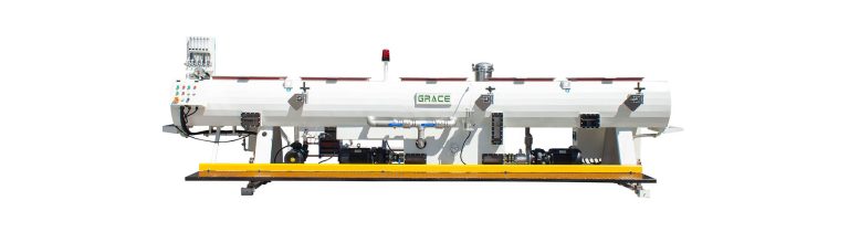
PRODUCT OVERVIEW
Designed around the production task.
Vacuum tank and spray tank configurations for controlled pipe geometry, surface quality and reliable downstream handling.
EQUIPMENT REFERENCE
Confirmed equipment, followed by the process context.
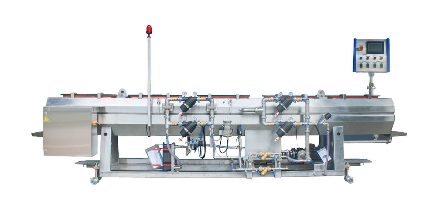
Vacuum tank & spray tank
Vacuum sizing and spray cooling work together to support controlled pipe calibration and temperature reduction. Tank type, quantity and length are defined around material, pipe range, line speed, water conditions and the available factory layout.
High-efficiency spray nozzle
High-efficiency spray nozzles are arranged to support even coverage and practical cooling control. Nozzle layout, spray angle and maintenance access are selected for the specified pipe range and line conditions.
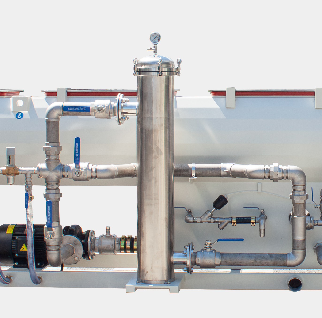
Stainless steel filter
A stainless steel filtration arrangement supports practical circulation-water management. Filtration fineness, flow and cleaning intervals are defined around water quality and operating conditions.
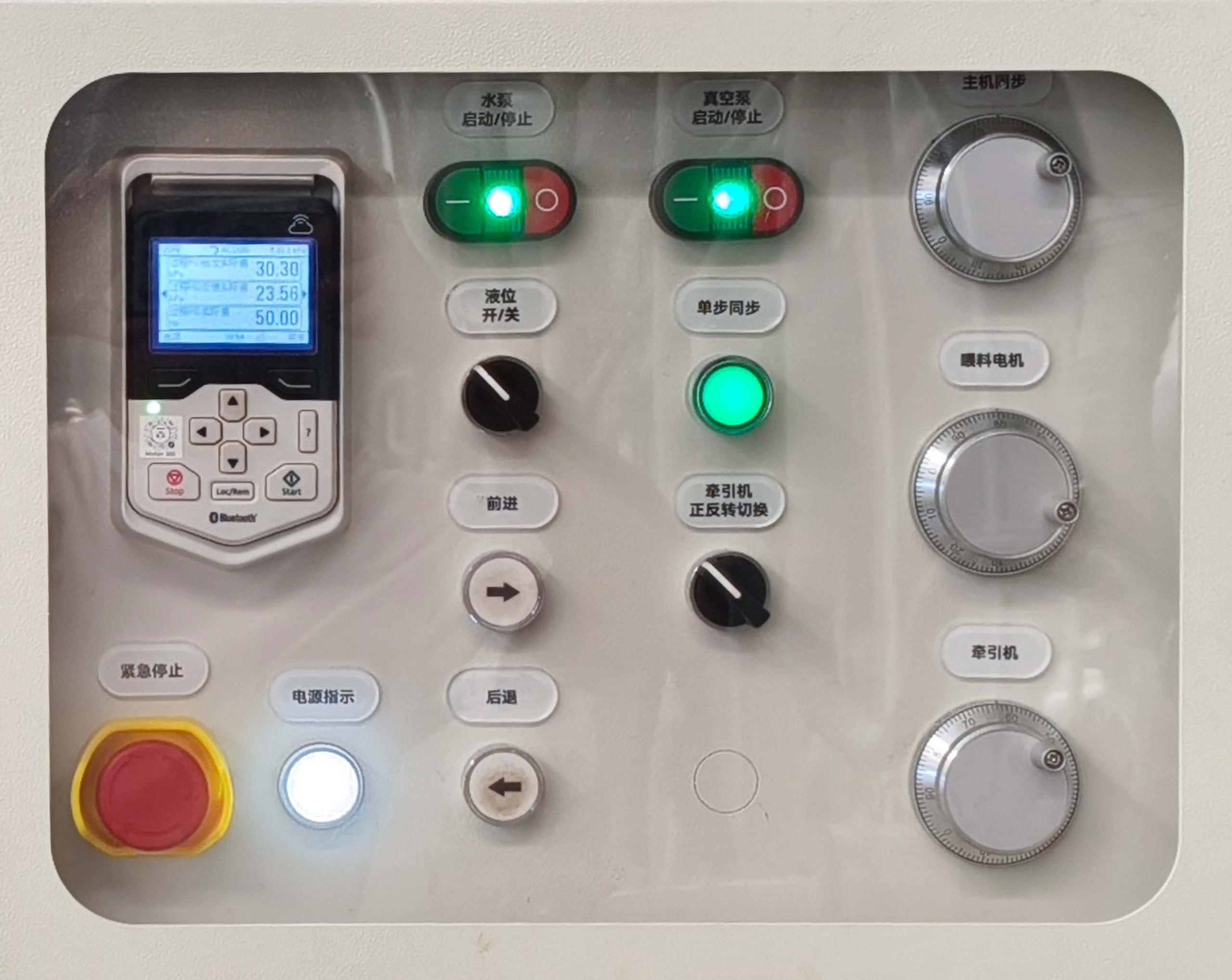
Variable-frequency energy saving
Variable-frequency control can be configured to match vacuum and water-management demand to the operating condition. Final energy performance is confirmed for the selected equipment and project conditions.
CONFIGURATION ENGINEERING
Sizing and cooling defined by the pipe, water conditions and layout
Vacuum sizing and spray cooling are engineered as a connected pipe-calibration and temperature-management route. Tank type, quantity and effective length are defined from the material, complete pipe schedule, line duty, water conditions and usable factory layout.
Pipe geometry & calibration
The pipe range, wall schedule, material behaviour and surface requirement define the calibration task. Vacuum capacity, sealing arrangement and tank layout are reviewed for the selected pipe rather than selected by diameter alone.
Cooling circuit & water management
Spray coverage, circulation, filtration and water-management arrangements are configured around the available water conditions and cooling duty. The project defines practical maintenance access and the required interface with the utility system.
Tank length & line layout
Tank number, effective cooling length, centre height and equipment interfaces are planned with the available factory length, operating rate and adjoining haul-off arrangement. These items are confirmed with the complete line layout.
Project options
Vacuum and water-control functions, nozzle layout, filtration, heat exchange and measurement interfaces can be configured for the declared project requirements. Their final scope follows the agreed pipe range and utility conditions.
FOR A TECHNICAL PROPOSAL
Information that lets us define the right line.
- Pipe material and complete OD × wall-thickness / SDR schedule
- Target operating rate and number of outlets
- Inlet-water temperature, flow, water quality and circulation arrangement
- Available factory length, centre height and adjoining equipment interfaces
- Surface-quality and measurement requirements
- Site utility, maintenance and automation expectations
Tank selection, cooling length, water demand and energy performance are project calculations, not universal catalogue values. The final configuration is verified with the selected material, pipe schedule and complete line layout.
TECHNICAL DATA
Vacuum tank & spray tank model range
| Equipment | Model | Pipe range | Length | Process arrangement |
|---|---|---|---|---|
| Vacuum tank | GMVT63A-9/1 | φ16–63 mm | 9 m | Single chamber; −0.01 to −0.06 MPa |
| Vacuum tank | GMVT315A-9/2 | φ50–315 mm | 9 m | Dual chamber; −0.01 to −0.06 MPa |
| Vacuum tank | GMVT450A-9/1 | φ110–450 mm | 9 m | Single chamber; −0.01 to −0.06 MPa |
| Vacuum tank | GMVT630A-9/1 | φ250–630 mm | 9 m | Single chamber; −0.01 to −0.06 MPa |
| Vacuum tank | GMVT800A-9/1 | φ400–800 mm | 9 m | Single chamber; −0.01 to −0.06 MPa |
| Vacuum tank | GMVT1200A-9/1 | φ630–1,200 mm | 9 m | Single chamber; −0.01 to −0.06 MPa |
| Vacuum tank | GMVT1600A-10/1 | φ800–1,600 mm | 10.5 m | Single chamber; −0.01 to −0.06 MPa |
| Spray tank | GMST63A-9 | φ16–63 mm | 9 m | 4 spray pipes |
| Spray tank | GMST315A-9 | φ75–315 mm | 9 m | 6 spray pipes |
| Spray tank | GMST450A-9 | φ110–450 mm | 9 m | 8 spray pipes |
| Spray tank | GMST630A-9 | φ250–630 mm | 9 m | 8 spray pipes |
| Spray tank | GMST800A-9 | φ400–800 mm | 9 m | 10 spray pipes |
| Spray tank | GMST1200A-9 | φ630–1,200 mm | 9 m | 12 spray pipes |
| Spray tank | GMST1600A-9 | φ800–1,600 mm | 9 m | 16 spray pipes |
Vacuum tank
- Model
- GMVT63A-9/1
- Pipe range
- φ16–63 mm
- Length
- 9 m
- Process arrangement
- Single chamber; −0.01 to −0.06 MPa
Vacuum tank
- Model
- GMVT315A-9/2
- Pipe range
- φ50–315 mm
- Length
- 9 m
- Process arrangement
- Dual chamber; −0.01 to −0.06 MPa
Vacuum tank
- Model
- GMVT450A-9/1
- Pipe range
- φ110–450 mm
- Length
- 9 m
- Process arrangement
- Single chamber; −0.01 to −0.06 MPa
Vacuum tank
- Model
- GMVT630A-9/1
- Pipe range
- φ250–630 mm
- Length
- 9 m
- Process arrangement
- Single chamber; −0.01 to −0.06 MPa
Vacuum tank
- Model
- GMVT800A-9/1
- Pipe range
- φ400–800 mm
- Length
- 9 m
- Process arrangement
- Single chamber; −0.01 to −0.06 MPa
Vacuum tank
- Model
- GMVT1200A-9/1
- Pipe range
- φ630–1,200 mm
- Length
- 9 m
- Process arrangement
- Single chamber; −0.01 to −0.06 MPa
Vacuum tank
- Model
- GMVT1600A-10/1
- Pipe range
- φ800–1,600 mm
- Length
- 10.5 m
- Process arrangement
- Single chamber; −0.01 to −0.06 MPa
Spray tank
- Model
- GMST63A-9
- Pipe range
- φ16–63 mm
- Length
- 9 m
- Process arrangement
- 4 spray pipes
Spray tank
- Model
- GMST315A-9
- Pipe range
- φ75–315 mm
- Length
- 9 m
- Process arrangement
- 6 spray pipes
Spray tank
- Model
- GMST450A-9
- Pipe range
- φ110–450 mm
- Length
- 9 m
- Process arrangement
- 8 spray pipes
Spray tank
- Model
- GMST630A-9
- Pipe range
- φ250–630 mm
- Length
- 9 m
- Process arrangement
- 8 spray pipes
Spray tank
- Model
- GMST800A-9
- Pipe range
- φ400–800 mm
- Length
- 9 m
- Process arrangement
- 10 spray pipes
Spray tank
- Model
- GMST1200A-9
- Pipe range
- φ630–1,200 mm
- Length
- 9 m
- Process arrangement
- 12 spray pipes
Spray tank
- Model
- GMST1600A-9
- Pipe range
- φ800–1,600 mm
- Length
- 9 m
- Process arrangement
- 16 spray pipes
This is a representative preliminary selection range. Final tank type, quantity and length must be calculated from material, complete DN × SDR or wall-thickness schedule, target output and line speed, inlet-water temperature and flow, available factory length, centre height and adjoining equipment interfaces.