
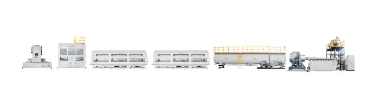
SEE IT IN OPERATION
HDPE pipe extrusion line
Start with the line in operation, then explore its principal process stations and the available model range.
HDPE PIPE EXTRUSION
A complete line, configured around the pipe.
Grace HDPE pipe extrusion lines are configured around pipe diameter, wall thickness, output and downstream requirements. The platform combines extrusion, control, die-head, calibration, haul-off and cutting into one coordinated system for pipe producers seeking dependable production across a broad range of specifications.
CONFIGURATION ENGINEERING
Engineering an HDPE pipe line around the complete production duty
An HDPE pipe line is defined from the resin, pipe schedule and operating duty as one system. Diameter alone does not determine the extruder, die, cooling length, haul-off or cutting arrangement; each station has to remain balanced with the selected wall thickness, output objective and site conditions.
Pipe schedule & material route
The technical starting point is the complete OD × SDR or wall-thickness schedule, resin grade, single- or multi-layer structure and target application. This information defines the melt, die and downstream conditions that the line must support.
Extrusion & die head
The 40 L/D extrusion platform and die-head arrangement are matched to the selected PE or PP material, diameter range, wall schedule and required layer structure. Co-extrusion, stripe and marking arrangements are reviewed as part of the complete product definition.
Sizing, cooling & factory layout
Vacuum sizing and multi-stage cooling are calculated around wall thickness, operating rate, inlet-water conditions and the usable factory length. Cooling capacity is a line-level engineering decision, not an accessory chosen after the extruder.
Traction, cutting & handling
Haul-off track arrangement, contact length, cutting method, pipe support and handling are selected around pipe weight, line speed, required surface protection and the finished-pipe specification.
FOR A TECHNICAL PROPOSAL
Information that lets us define the right line.
- Resin grade, intended application and single- or multi-layer pipe structure
- Complete OD × SDR or wall-thickness schedule, including all required sizes
- Target rate for key sizes, number of outlets and production pattern
- Marking, stripe, co-extrusion, cutting length, handling and packing requirements
- Factory effective length, cooling-water temperature and flow, electrical supply and site constraints
- Required standards, quality-control points, automation and service expectations
The published platform table is a representative planning guide. Final output, cooling length, energy use, tooling, quality criteria and contractual performance are released only through project-specific technical review and FAT criteria.
MODEL RANGE
Select the line around your production requirement.
| Platform | Pipe range | 40 L/D extruder configuration | Main power (kW) | Typical output |
|---|---|---|---|---|
| PE63H Dual-outlet | DN20–63 | GMSE60/40-A200 | 200 | 700–750 kg/h |
| PE110H | DN20–110 | GMSE60/40-A200 | 200 | 700–750 kg/h |
| PE160H | DN40–160 | GMSE60/40-A200 | 200 | 700–750 kg/h |
| PE250H Economy | DN50–250 | GMSE60/40-A200 | 200 | 700–750 kg/h |
| PE250H High-output | DN50–250 | GMSE75/40-A315 | 315 | 1,000–1,100 kg/h |
| PE315H | DN50–315 | GMSE75/40-A315 | 315 | 1,000–1,100 kg/h |
| PE630H Standard | DN250–630 | GMSE75/40-A315 | 315 | 1,000–1,100 kg/h |
| PE630H High-output | DN250–630 | GMSE90/40-A450 | 450 | 1,600 kg/h* |
| PE800H | DN315–800 | GMSE90/40-A450 | 450 | 1,600–1,700 kg/h |
| PE1600H | DN710–1,600 | 2 × GMSE75/40-A315 | 630 | Up to 2,000 kg/h |
Typical outputs are preliminary platform-selection values, not unconditional contractual guarantees. Final stable line output must be verified against resin grade, pipe diameter and SDR or wall thickness, die throughput, cooling-water conditions, available cooling length, haul-off capacity and cutting cycle. *The PE630H high-output value also remains subject to die-throughput verification.
LINE CONFIGURATION
Every process station has a defined role.
 Explore this equipment →
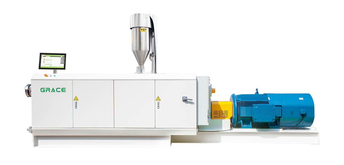
40 L/D single-screw extruder
The 40 L/D single-screw extruder is configured for HDPE and PP pipe production where stable melt quality matters. Its screw and process-control design is intended to support consistent wall thickness, pressure stability and controlled melt temperature for large-diameter and thick-wall pipe applications.
View equipment page →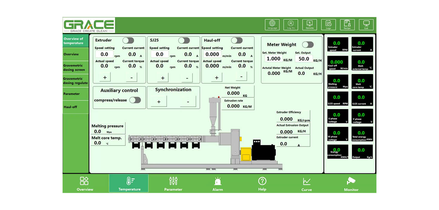
PLC control system
A clear operator interface brings together the main production values, including speed, temperature and pressure. The control concept supports practical recipe management, day-to-day process monitoring and coordinated operation of the line, helping operators work from one consistent production view.
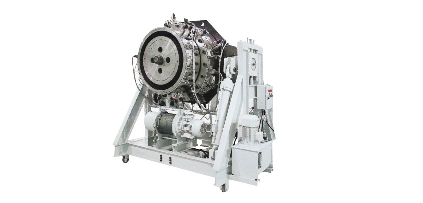
Die head
The die-head flow path is designed to promote even wall-thickness distribution while maintaining a controlled melt-temperature profile. The double-split support concept is engineered to reduce material use compared with a single-split arrangement while supporting sound pipe mechanical performance.
 Explore this equipment →
Vacuum tank
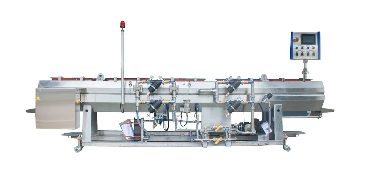
The vacuum and spray tank is designed around stable calibration and practical cooling control. Adjustable spray nozzles enlarge the cooling area, while automatic water management supports routine operation. Central vacuum and heat-exchange configurations are available where the project calls for them.
View equipment page →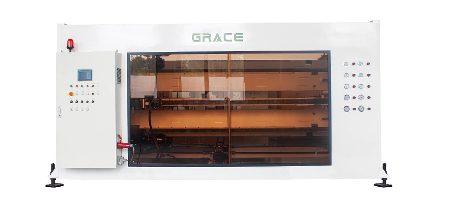 Explore this equipment →
Haul-off
The haul-off unit can be configured with a single drive or independently driven caterpillars. Servo synchronization, high-grip rubber blocks and an anti-stretch chain design are intended to give the pipe controlled traction while helping protect pipe geometry through the downstream process.
View equipment page →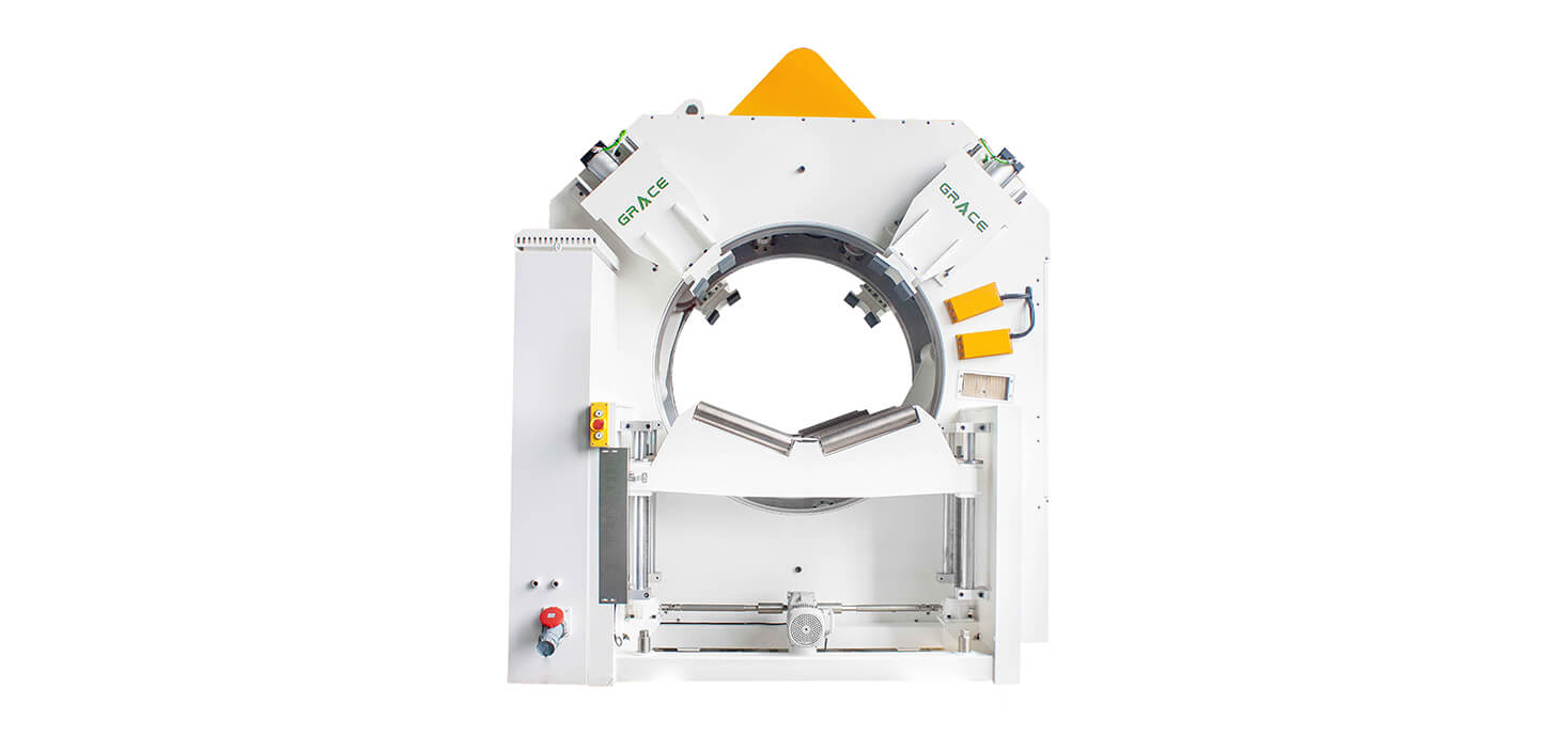 Explore this equipment →
Chip-free cutting
For larger pipe dimensions, the chip-free cutter provides a controlled downstream cutting option within this HDPE pipe-line platform. Recipe-based operation and real-time cutting-data visibility help keep the final process station aligned with the selected pipe specification.
View equipment page →